Understanding how a keyboard matrix circuit works! AskElectronics
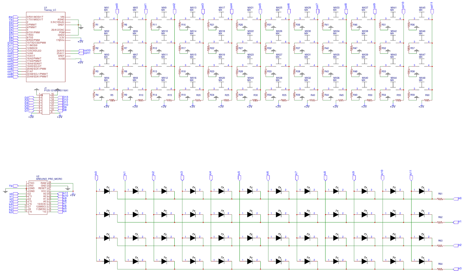
The rows and columns of the keyboard matrix are connected directly to the pin headers so that the keyboard can be connected to an Arduino or any other microcontroller. It is perfect for prototyping your projects that will include an integrated keyboard.

Keyboard matrix circuit Wikipedia, the free encyclopedia keyboard
Step 1: What's Inside the Keyboard? This depends on what kind of keyboard you're taking apart. Most keyboards tend to have a rubbery membrane with indentations which are flattened when you press a key.
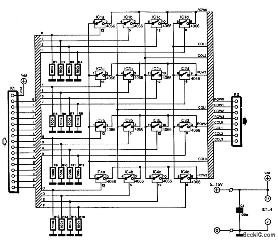
KEYBOARD_MATRIX_INTERFACE Basic_Circuit Circuit Diagram
A keyboard matrix circuit is a design used in most electronic musical keyboards and computer keyboards in which the key switches are connected by a grid of wires, similar to a diode matrix. For example, 16 wires arranged in 8 rows and 8 columns can connect 64 keys—sufficient for a full five octaves of range . By scanning these crossings, a keyboard controller can determine which keys are.
Matrix Scanning 1v Octave Keyboard Circuit
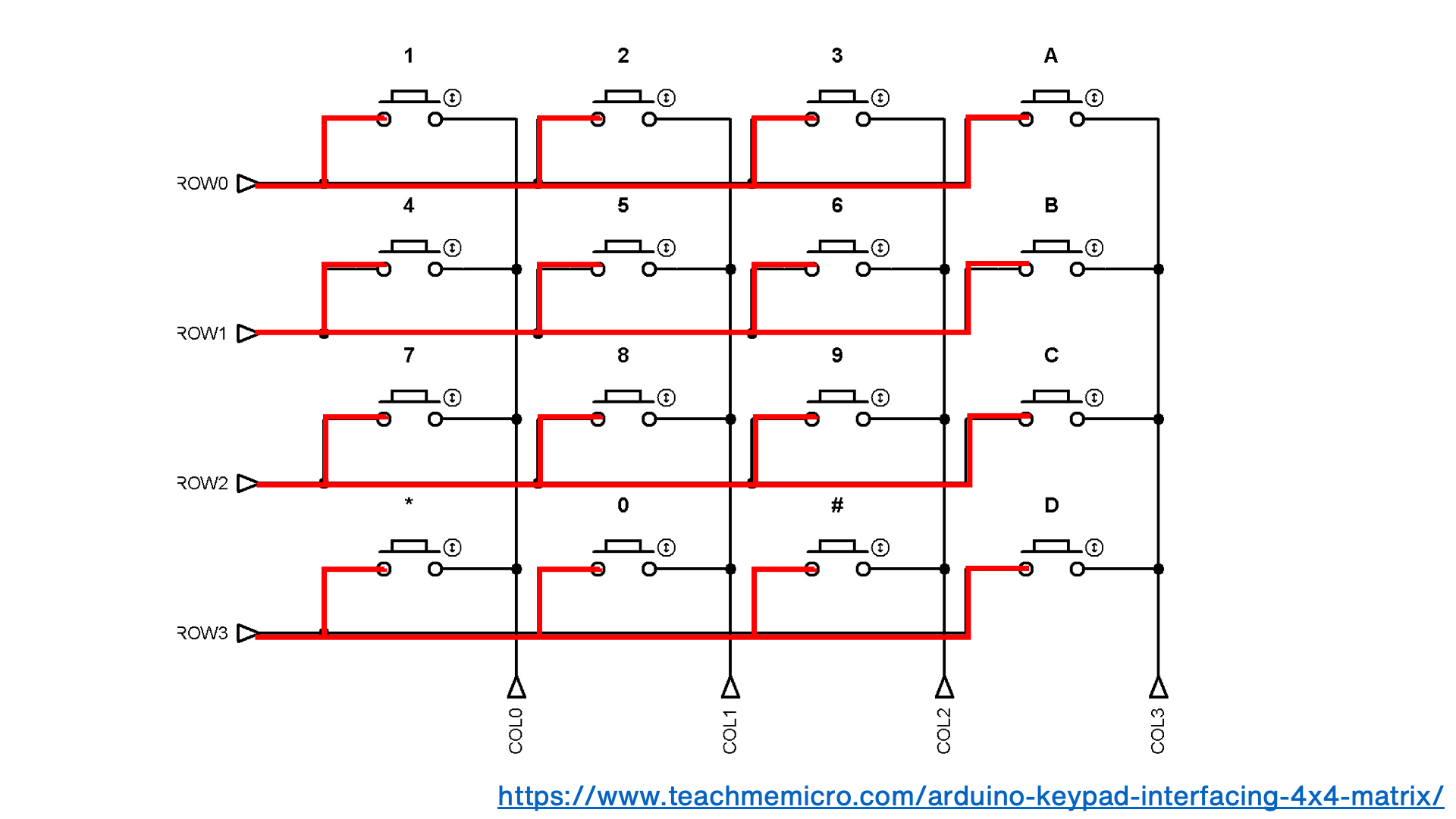
How does a keyboard matrix work? help I'm doing a presentation on how keyboards work for a school project, and I understand the basics. Current travels from a column wire, flows through the open switch to a row wire, and back to the computer. The computer can use the data to tell which switch in the matrix was closed to produce such a result.
Arduino Keyboard Matrix Code and Hardware Tutorial Bald Engineer
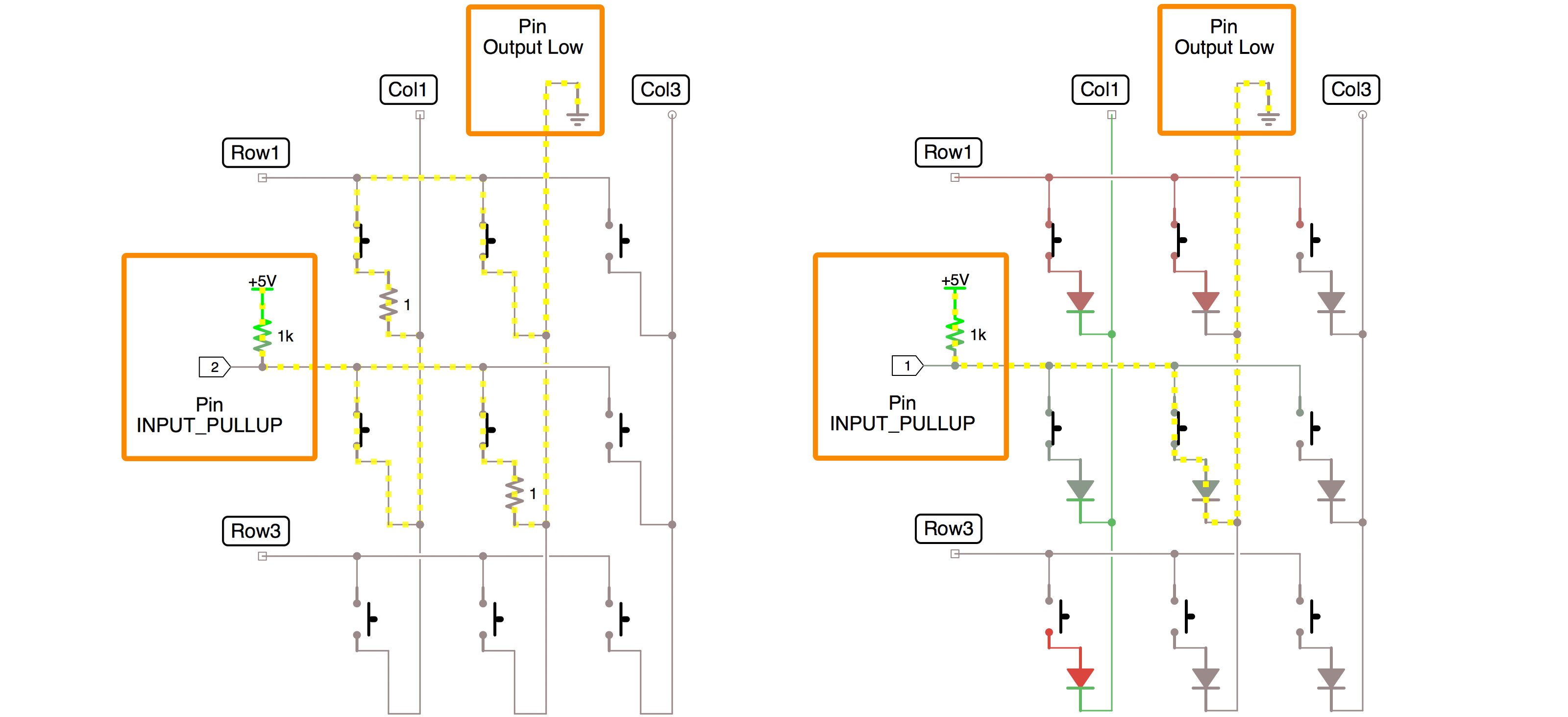
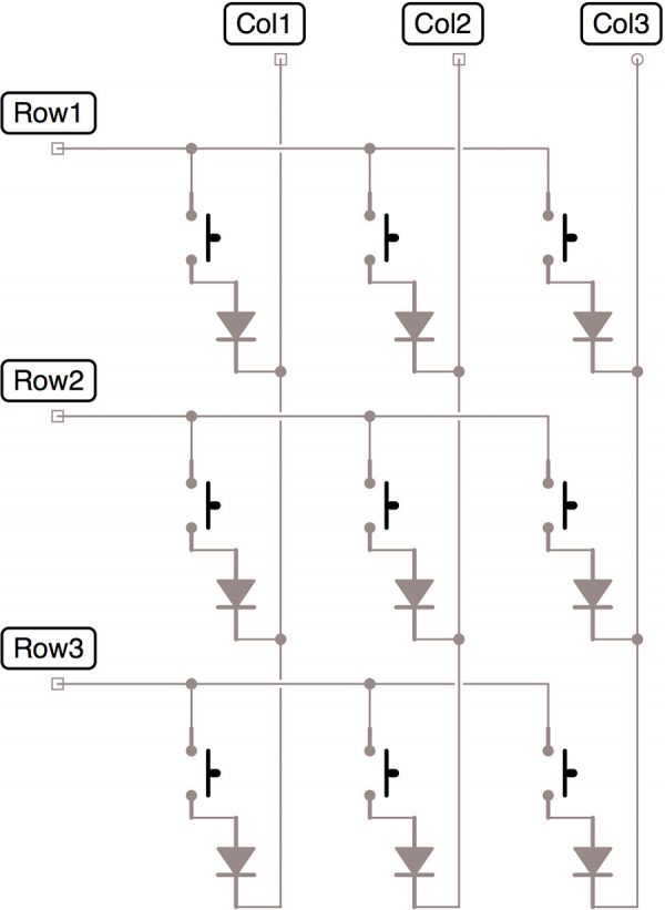
Building a keyboard matrix. I want to build a 7 Rows x 15 Columns keyboard from scratch, thus I have started from the theoretical design of the matrix. The classic way should be to assign directly the Rows and Columns to (7+15) I/O of a microcontroller and also connect 7X15 diodes to every each switch in order to prevent the "ghost" effect.

Figure 1 from Design and realization of general matrix keyboard based
Purpose. This paper presents a novel design method for keyboard circuits. The purpose of this study is to enable a single-board computer with fewer pins to recognize a keyboard system consisting of a large number of switches. Through the study of different kinds of keyboard circuits, a general circuit schematic design method is abstracted.

Gammon Forum Electronics Microprocessors Using a keypad matrix
A matrix keyboard or a keyboard matrix circuit is a keyboard featuring a grid-like array of wires connecting the key switches. So, for instance, if the keyboard has eight rows and eight columns of wire, it can support 64 keys. These wires have switches at the intersection.
40 Keyboards Analog matrix keyboard
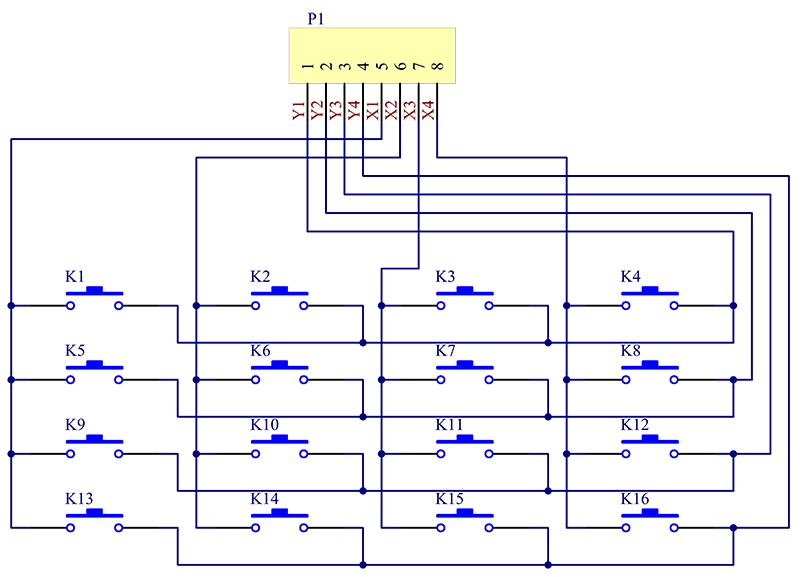
A keyboard matrix is a system used to connect the buttons or keys of a keyboard to the microcontroller or circuit that registers keypresses. In a keyboard matrix, the keys are arranged in a grid or matrix pattern, with rows and columns. Each key in the matrix is assigned a unique combination of one row and one column.
How a Calculator Works The EduVisa Blog
Conceptual Matrix Circuit This keyboard only has 4 keys: A , B, C, and D. Each key has a unique grid location, much like points on a graph. Key A is at node C1R1, key B is at node C2R1, key C is at node C1R2, and key D is at node C2R2. In reality this is pretty useless which is why real keyboards use many more rows and columns.
De Blauwe Schicht!
The key matrix is a grid of circuits underneath the keys. In all keyboards (except for capacitive models, which we'll discuss in the next section), each circuit is broken at a point below each key. When you press a key, it presses a switch, completing the circuit and allowing a tiny amount of current to flow through.
Arduino Keyboard Matrix Code and Hardware Tutorial Bald Engineer
In the most basic sense, a keyboard matrix circuit is a type of keyboard that features a grid-like array of wires connecting the key switches (hence the name). If the keyboard features 8 rows and 8 columns of wires, for instance, it can support up to 64 keys. The switches are located at the intersection of these wires.

20Key Matrix Keypad That Uses Four Microcontroller Pins Jameco
Conceptual Matrix Circuit This keyboard only has 4 keys: A , B, C, and D. Each key has a unique grid location, much like points on a graph. Key A is at node C1R1, key B is at node C2R1, key C is at node C1R2, and key D is at node C2R2. In reality this is pretty useless which is why real keyboards use many more rows and columns.
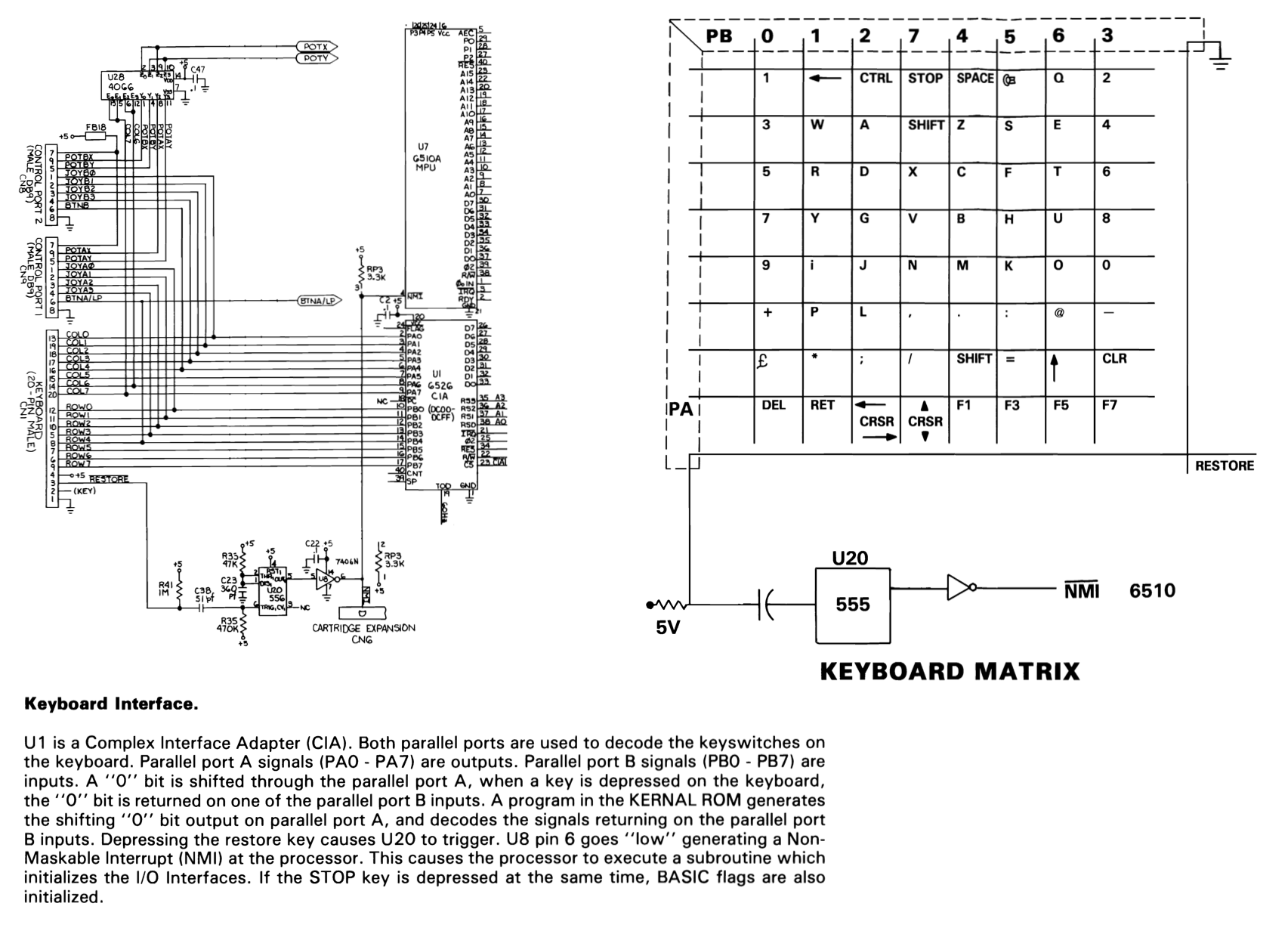
Commodore Plus 4 Service Manual PCB Schematic Diagrams and Keyboard Matrix
Attempts to explain how a keyboard matrix works, what "ghosting" and "masking" are, and how to prevent them. Table of Contents 1. Introduction 2. The Matrix Circuit 3. Scanning to Detect Key Presses 4. Single Key Presses 5. Multiple Key Presses 6. Three Simultaneous Key Presses and Ghosting 7.
keyboard matrix wiring diagram rows Blog My Wiki!
A keyboard matrix circuit is a design used in most electronic musical keyboards and computer keyboards in which the key switches are connected by a grid of wires, similar to a diode matrix. For example, 16 wires arranged in 8 rows and 8 columns can connect 64 keys—sufficient for a full five octaves of range (61 notes).

The keyboard of the MZ700
The trick is to use a keyboard matrix (e.g. 5 rows x 15 columns) and quickly cycle through each row/column, allowing you to use 2n pins only for a n x n matrix. You can read more about how.
4 x 4 matrix keypad converter
A keyboard matrix circuit is a design used in most electronic musical keyboards and computer keyboards in which the key switches are connected by a grid of wires, similar to a diode matrix.For example, 16 wires arranged in 8 rows and 8 columns can connect 64 keys—sufficient for a full five octaves of range (61 notes). By scanning these crossings, a keyboard controller can determine which.